
Turck product news
Keep the analog sensor. Add an IO-Link path.
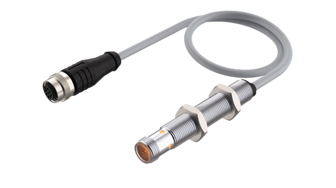
Turck's ILC Analog to IO-Link Inline Converter gives facilities a compact retrofit option when an existing analog sensor remains suitable but the controls strategy calls for IO-Link connectivity.
What Turck's converter adds
Analog input flexibility
Turck lists adjustable current inputs of 0-20 mA and 4-20 mA, plus voltage ranges of 0-5 V, 1-6 V, and 0-10 V.
Inline installation
The cylindrical M12-format device connects directly to an analog sensor through its 300 mm lead and provides an M12 IO-Link connection toward the master.
Parameterization options
The converter is parameterizable through IO-Link, including use with Turck Automation Suite. Turck also identifies optional timer delays and switching-output functions for alarm or trip-amplifier use.
Operational implications
Phased upgrades
A converter can support staged modernization when wholesale sensor replacement is unnecessary or impractical.
Configuration consistency
IO-Link parameterization can bring the converted point into the same engineering workflow as other IO-Link devices.
Application review remains essential
Signal range, wiring, environmental conditions, power budget, IO-Link master behavior, and required control response must be checked before selection.
Designer and implementation checks
Confirm the signal
Match the sensor's current or voltage output to a supported input range and confirm the required scaling in the control system.
Check the physical interface
Review M12 pinout, cable length, mounting space, strain relief, ingress protection, and the ambient-temperature range for the installation.
Plan commissioning
Confirm the master's IO-Link port configuration, IODD handling, process-data mapping, diagnostics, and any switching or timing behavior before production release.
How can BEA help?
BEA can help evaluate whether the Turck ILC is a good fit for an existing analog sensing point, review the connection to the selected IO-Link master, and support parameterization and commissioning planning. Final selection should be based on the sensor signal, electrical design, environmental requirements, and machine or process risk.
Read Turck's product announcement | Review the official product details
Industrial reliability and municipal controls
Surge Protection: Why Industrial and Municipal Facilities Cannot Afford to Ignore It
Modern plants, pump stations, lift stations, well houses, and utility systems depend on electronics that are productive, diagnostic-rich, and vulnerable to short electrical disturbances. A transient event that lasts only a fraction of a second can damage a PLC, corrupt communications, trip a drive, or leave a field device weakened enough to fail later.
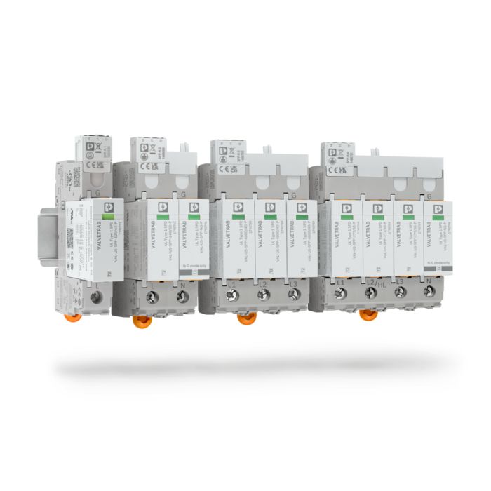
Illustration: how a surge protector works
When voltage rises suddenly, the surge protective device provides a preferred path for transient energy. It clamps the overvoltage and diverts surge current toward the grounding and bonding system, helping keep the remaining voltage at the protected equipment within a safer range for the application.
Normal operation
The SPD remains inactive while system voltage is within its intended operating range.
During the transient
The SPD conducts surge current and limits the voltage passed downstream. The exact protection depends on device selection and installation.
After the event
Status indicators, alarm contacts, or replaceable modules should be checked so the site is not left unknowingly unprotected.
What a surge is
An electrical surge, or transient overvoltage, is a brief voltage increase above the normal operating level. A surge protective device limits that transient energy by diverting or restricting surge current before it reaches vulnerable electronics.
Where it comes from
Lightning is only one source. Utility switching, motor starts and stops, contactors, solenoids, VFDs, capacitor banks, generator transfers, faults, and long outdoor conductors can all place surge energy into a facility.
Why it matters
Industrial and municipal systems combine sensitive controls, inductive loads, long cable runs, outdoor equipment, and remote structures. That mix gives transient voltage many possible entry paths.
Protecting only the main feed is not enough
A surge can enter through any connected conductor. Main power protection may reduce one exposure, but it does not automatically protect a level transmitter, Ethernet cable, telephone circuit, radio coax, buried instrumentation line, or remote I/O connection.
Municipal sites
- Lift stations and well houses
- Pump control panels and VFDs
- Flow, pressure, and level transmitters
- Cellular, licensed radio, and antenna systems
Industrial sites
- PLC and HMI cabinets
- Machine panels and MCCs
- Ethernet and serial communication networks
- Remote instruments and interbuilding wiring
Surge damage is not always immediate
Some events create obvious failures: a power supply stops, a PLC fails, or a drive refuses to restart. Other events weaken components and create problems that are harder to connect to the original disturbance.
Control symptoms
Intermittent PLC faults, unexpected HMI or computer reboots, failed I/O channels, and repeated power-supply failures can all follow transient exposure.
Signal symptoms
Drifting analog readings, unstable instrument signals, damaged Ethernet ports, radio failures, and unexplained communication losses can consume troubleshooting time long after the event.
Process risk
For water, wastewater, utility, and production systems, the cost is not limited to replacement hardware. Downtime, emergency service, data loss, regulatory impact, or process interruption may be the larger concern.
A UPS is not a complete surge-protection system
A UPS is useful for ride-through power and controlled shutdown. It should not be treated as a substitute for properly selected surge protective devices, grounding, bonding, circuit protection, and electrical-system design.
A layered approach is normally required
1. Service and distribution
Protection near the incoming service or primary distribution equipment helps reduce larger transient events entering from the utility or facility distribution system.
2. Branch and control panels
Additional devices at distribution panels, MCCs, pump panels, machine panels, and automation cabinets place protection closer to PLCs, drives, HMIs, power supplies, and network equipment.
3. DC power and signals
Low-voltage circuits may need separate protection for 24 VDC power, analog loops, digital I/O, RTDs, thermocouples, Ethernet, serial communication, telephone lines, and radio coax.
4. Remote equipment
Long outdoor runs and cables between structures often deserve attention at both ends so field devices and panels are not left exposed from the remote side.
Panel and MCC placement: where surge protection is commonly applied
The most useful illustration for a plant or municipal site is not a generic building. It is the electrical path: incoming service protection to reduce larger utility-side events, MCC or distribution protection close to motor-control equipment, and branch or control-panel protection near PLCs, drives, power supplies, and communications.
Incoming service or switchgear
First layer for larger transients entering from utility switching, restoration, faults, or nearby lightning induction.
Main MCC or distribution panel
A second layer close to motor starters, VFD feeders, pump loads, and distribution equipment helps reduce residual transient voltage.
PLC, VFD, and branch panels
Protection near the control load is commonly paired with separate devices for 24 VDC, analog, Ethernet, serial, or radio/coax circuits.
Grounding, bonding, and installation details decide effectiveness
An SPD needs a low-impedance path to divert transient energy. Long leads, poor bonding, corroded connections, separated grounding systems, or poor routing can reduce performance even when the device itself is appropriate.
- Keep SPD conductors short and direct.
- Bond control-panel enclosures correctly.
- Verify grounding-electrode connections and interbuilding bonding.
- Address shield grounding and cable routing.
- Separate sensitive wiring from high-energy conductors where practical.
Inspection should be part of maintenance
Surge protective devices can absorb or divert repeated transient events over time. Many industrial devices include visual status indication, replaceable modules, remote alarm contacts, end-of-life indication, or monitoring points that can be wired into PLC or SCADA systems.
That status is especially useful at unmanned lift stations, well houses, and remote telemetry sites. Operators should know when a module needs inspection or replacement instead of assuming the site remains protected after storms or utility disturbances.
Selection factors
- System voltage and phase configuration
- Grounding configuration and installation location
- Short-circuit current rating and available fault current
- Maximum continuous operating voltage and voltage protection rating
- Signal type, communication speed, and environment
- Remote monitoring needs and upstream/downstream coordination
Standards and product evaluation
UL 1449 is the primary North American product safety standard associated with low-voltage SPDs. A listed or evaluated device still has to be selected and installed for the actual electrical system, signal type, environment, and maintenance expectation.
UL Solutions surge protection device testing and certification
How BEA can help
Britton Electronics & Automation can evaluate surge-protection needs during a new control-system design, panel replacement, facility upgrade, or preventative-maintenance inspection. BEA can help identify surge-entry paths across electrical services, PLC cabinets, VFD panels, water and wastewater sites, remote telemetry, instrumentation, Ethernet networks, radio systems, outdoor wiring, and existing grounding and bonding systems.
BEA can also incorporate surge-device status contacts into PLC or SCADA systems so operators receive an alarm when protection needs attention. Surge protection cannot prevent every electrical failure, but a properly designed and maintained system can reduce avoidable damage, unexplained control problems, and costly downtime.
Phoenix Contact surge protection for North American supply systems
Control panel power supply selection
A 24 VDC supply is more than voltage and amperage
A calculated 7 amp panel load can make a 10 amp, 24 VDC supply look like an easy selection. Under steady operation, that may be true. The real question is how the supply behaves when devices start together, a capacitive load energizes, incoming power sags, or one branch circuit faults.
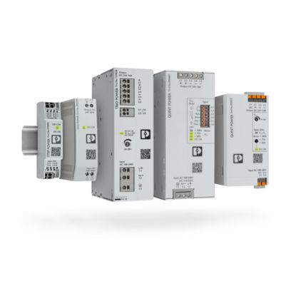
Phoenix Contact offers UNO POWER, TRIO POWER, and QUINT POWER families for different application needs. Selecting between them should be an engineering decision based on load behavior, system availability, diagnostics, fault clearing, and future serviceability.
The problem with nameplate-only selection
Voltage and continuous current are necessary checks, but they do not describe startup reserve, overload behavior, short-circuit response, monitoring, or how one failed field circuit affects the rest of the panel. A supply that is acceptable for a small steady load may be a poor fit for a pump station, process panel, or remote system where losing the 24 VDC bus creates downtime and confusing fault symptoms.
UNO POWER
Compact basic power for stable, predictable loads. UNO can fit small enclosures and dedicated auxiliary equipment where advanced monitoring or selective fault clearing is not required.
- Small instrumentation panels
- Remote monitoring enclosures
- Operator interfaces or communication devices
- Constant, noncritical DC loads
TRIO POWER
Standard industrial power for machine and system loads with more dynamic behavior. TRIO can be appropriate where reserve capability, diagnostics, and cost balance matter.
- Machine control panels
- Conveyor and solenoid systems
- Distributed I/O panels
- Moderate startup demand
QUINT POWER
Maximum-functionality power for critical applications where reserve, diagnostics, configurable behavior, and fault-clearing support can protect system availability.
- Municipal water and wastewater systems
- Lift and pump stations
- Remote unattended panels
- Processes where restarting is difficult
Why fault current matters
Consider a panel with separate DC branches for the PLC, remote I/O, operator interface, network switch, instrumentation, relays, solenoids, and field devices. If one field cable shorts, the preferred result is for the protective device on that branch to trip quickly while the unaffected control circuits remain powered.
A current-limiting supply may reduce output before a standard miniature circuit breaker receives enough current to trip magnetically. The faulted branch then drags down the whole 24 VDC bus while protection responds slowly or the control system resets first.
Selective Fuse Breaking is a system design tool
Phoenix Contact describes QUINT POWER supplies with SFB Technology as supporting selective tripping of standard miniature circuit breakers so parallel loads can continue operating. The actual result still depends on the exact supply, breaker curve and rating, conductor size, wire length, connection resistance, and available short-circuit current.
When QUINT is worth specifying
One fault should not stop everything
In a coordinated design, a QUINT supply can help provide the short-duration current needed to clear a faulted branch while preserving power to PLCs, communications, and unaffected loads.
Temporary load demand matters
Some industrial computers, HMIs, network equipment, capacitive devices, solenoid banks, radios, and I/O assemblies demand more current during startup than during normal operation. Power reserve can support these events without simply oversizing continuous capacity.
Monitoring provides earlier warnings
More advanced supplies can provide status and signaling that help identify output voltage, current, reserve, or overload concerns before the DC bus fails and the root cause becomes harder to separate from the shutdown.
Future changes are likely
Panels often gain instruments, radios, Ethernet switches, I/O modules, relays, and monitoring equipment over time. A supply with useful reserve and diagnostics gives the system a better foundation for those additions.
When TRIO or UNO may be the better choice
TRIO may fit
TRIO POWER can be the right balance when the application has dynamic loads but limited consequences from a complete shutdown, moderate boost capability is enough, extensive preventive monitoring is unnecessary, and panel cost is a major constraint.
UNO may fit
UNO POWER can be the correct selection when the load is small and predictable, little starting current is required, DIN rail space is tight, the supply serves a dedicated device, and branch-circuit selectivity is not required.
Good engineering does not mean using the most expensive supply in every enclosure. It means matching the operating behavior of the power supply to the risk, load profile, and service expectations of the control system.
Questions to ask before selecting
- What is the normal continuous load?
- What is the maximum expected load?
- Are connected devices highly capacitive?
- Do loads have significant startup or inrush current?
- How much future expansion is expected?
- What happens if the 24 VDC bus shuts down?
- Must one failed branch be isolated while other circuits continue operating?
- What type and size of branch protection will be used?
- Are wire lengths and conductor sizes compatible with selective tripping?
- Does the PLC need advance warning of an overloaded power system?
- Is redundancy required?
- How difficult or expensive would restart be?
How can BEA help?
Britton Electronics & Automation can help evaluate control-panel power calculations, Phoenix Contact UNO, TRIO, and QUINT selection, DC branch-circuit coordination, breaker or electronic protection selection, voltage drop, redundancy, PLC monitoring, modernization, and recurring 24 VDC failures.
The right supply is not selected only for the day everything works normally. It is selected for how the panel should behave when a field circuit fails, a load starts hard, or the system grows beyond its original assumptions.
For additional manufacturer context, see Phoenix Contact's overview of power supplies, SFB Technology, and QUINT POWER maximum-functionality supplies.
Power factor is a capacity and efficiency signal
In an AC power system, some current does useful work and some current supports magnetic fields in equipment such as induction motors, transformers, and contactor coils. Power factor describes how much of the supplied apparent power is converted into real work at a given operating point.
A low power factor does not mean the motor is doing more mechanical work. It usually means the electrical system is carrying more current than necessary for the useful output being delivered.

What is power factor?
Power factor is the ratio between real power, measured in kilowatts (kW), and apparent power, measured in kilovolt-amperes (kVA). Reactive power, measured in kVAR, is the portion that circulates between the source and reactive loads without producing mechanical output.

The power triangle
The triangle is a useful way to explain the relationship: kW is useful work, kVAR is reactive demand, and kVA is the total electrical capacity the distribution system must support.

Lagging current
Many inductive loads draw current that lags voltage. The larger that phase difference becomes, the lower the displacement power factor becomes.
Why does power factor matter?
Good power factor
- Lower current for the same useful work
- Less heating in feeders, transformers, and switchgear
- Lower voltage drop under load
- More usable electrical capacity for production equipment
Poor power factor
- Higher current for the same useful work
- More I-squared-R losses and equipment heating
- Greater voltage drop during heavy loading
- Less available capacity before conductors or transformers reach limits
Utilities may also measure demand in ways that penalize poor power factor. Even when there is no direct penalty, low power factor can still consume distribution capacity that could otherwise support additional loads.
Capacitor banks
Capacitor banks are a common correction method for inductive loads. When applied correctly, they supply part of the reactive power locally, so less reactive current has to travel from the utility source through upstream conductors and transformers.
Before correction
The utility and upstream distribution equipment supply both real current and reactive current to the load. Feeders and transformers carry the combined current, which can increase heating and voltage drop.

After correction
A properly engineered capacitor bank near the load supplies reactive power locally. The motor mechanical load is unchanged, but upstream current can be reduced.
Do not confuse displacement power factor with harmonics
A facility with variable frequency drives may show good displacement power factor while still having harmonic distortion on the input current. That is why a power-quality review should look beyond a single power factor number when drives, rectifiers, or other nonlinear loads are present.
When to investigate power factor
- Utility bills show power factor penalties, kVA demand charges, or unexplained demand increases.
- Transformers, feeders, or switchgear are warm under normal production loading.
- Voltage drop appears when large motors, pumps, or blowers start or operate together.
- A facility is adding equipment and needs to understand available electrical capacity.
- Existing capacitor banks, contactors, or controllers are aging, disabled, or frequently faulting.
How BEA can help
BEA can help evaluate the practical side of power factor in industrial automation environments: reviewing electrical drawings, checking motor and drive applications, coordinating with qualified electrical personnel, and supporting power-quality measurements where appropriate. The right answer may be correction equipment, a settings or maintenance issue, a drive or harmonic review, or simply better visibility into how the electrical system behaves under real production load.
For facilities with motor-control centers, VFDs, pumps, blowers, and mixed automation loads, the best starting point is a measured assessment. That keeps recommendations tied to actual current, voltage, demand, and operating conditions instead of assumptions.
Selected illustration sources are public Wikimedia Commons files used as attributable technical image candidates; final image approval and licensing review should occur before publishing.
Motor control selection
VFD vs. Soft Starter: Why a VFD Can Be the Better Choice, Even at Full Speed
When planning a new pump installation or upgrading an existing motor control system, a common question is whether a variable frequency drive is worthwhile when the motor is expected to run at full speed. The answer depends on more than the start sequence.
The common question
Soft starters and variable frequency drives are often compared because both can reduce the electrical and mechanical shock associated with starting a motor. For a simple application that only needs controlled acceleration and then runs directly across the line, a soft starter may be a suitable and economical option.
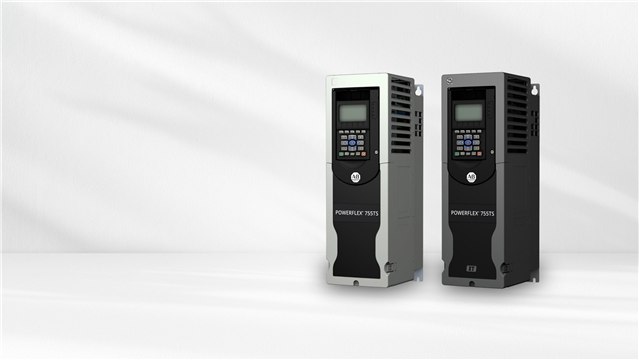
A VFD, however, does not stop adding value once the motor reaches 60 Hz. Even in constant-speed operation, the drive continues to manage the motor, monitor operating conditions, and provide information that can support troubleshooting and long-term system planning.
Mechanical stress still matters
Smooth acceleration and deceleration can reduce stress on pumps, bearings, couplings, belts, gearboxes, and piping systems. Even when the normal operating point is full speed, a controlled ramp can help reduce shock loads during starting and stopping.
Control system integration
Modern facilities increasingly depend on PLCs, HMIs, SCADA systems, and remote monitoring. A VFD can provide more than a run status bit. Depending on the drive and network options, operators may be able to monitor speed, current, power consumption, drive temperature, fault history, and operating status.
That information helps maintenance and operations teams see how the equipment is performing, not just whether it is running.
Practical selection checks
Which one is right?
There is no universal answer. If the application is simple, has minimal monitoring requirements, and is unlikely to require speed control, a soft starter may be the most economical choice.
When long-term flexibility, diagnostics, equipment protection, and integration with modern automation systems are priorities, a VFD often delivers greater operational value, even if the motor spends most of its life at full speed.
How can BEA help?
BEA can help evaluate the application, motor, pump curve, control requirements, available power, enclosure needs, communication options, and maintenance expectations before a starter or drive is selected. The best choice should account for today's operating requirement and the changes the system may need to support later.
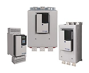
For additional manufacturer context, see Rockwell Automation's overview of PowerFlex low-voltage AC drives and SMC-50 soft starters.
BEA Blog
Why proper grounding is the foundation of a reliable control system
When an operator sees intermittent communication faults, unexplained PLC issues, inaccurate instrumentation, or nuisance VFD trips, it is natural to start with the device that appears to be misbehaving. In many facilities, the better first question is more basic: does the grounding system still provide a stable reference for the controls equipment?
Grounding does more than provide safety
Most people think of grounding strictly as a safety requirement, and that remains essential. For automation systems, grounding also gives sensitive electronics a stable electrical reference. PLCs, HMIs, VFDs, flow meters, level instruments, and industrial networks all rely on clean signals. When the grounding system is weak, noisy, corroded, or poorly bonded, those signals can become difficult to trust.
Common symptoms of grounding problems
Poor grounding can look like several different failures at once: intermittent PLC faults, random communication losses, erratic level readings, unstable flow measurements, drifting analog signals, nuisance VFD trips, Ethernet errors, or equipment resets after nearby lightning events. The frustrating part is that these symptoms are often sporadic, so replacing one component at a time may not solve the real problem.
Modern equipment is more sensitive
High-speed processors, Ethernet/IP networks, precision instruments, remote monitoring hardware, wireless devices, and VFDs all increase the importance of noise control and reference stability.
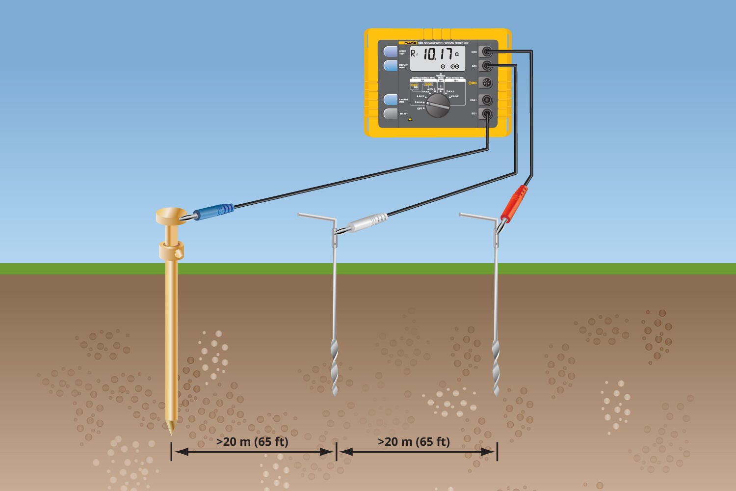
Ground resistance matters
Soil conditions, corrosion, damaged conductors, and aging ground rods can raise resistance over time. Routine testing helps catch changes before they become operational problems.
Good grounding is a system
Bonding, conductor sizing, low-resistance connections, surge protection, shield termination, and manufacturer-recommended installation practices all work together.
Do not chase symptoms without checking the foundation
When automation faults repeat, replacing sensors, PLC modules, drives, or network hardware may only hide the issue temporarily. If the underlying grounding problem remains, the same behavior can return later. Reviewing grounding health can reduce unnecessary part replacement, shorten troubleshooting time, and improve long-term system reliability.
A strong foundation for reliable automation
Reliable automation starts before the PLC program is written and before the first motor is started. A properly designed and maintained grounding system supports stable signals, safer installations, and longer equipment life. Whether a team is commissioning a new facility or maintaining an existing one, grounding deserves the same practical attention as controls programming, panel design, network layout, and instrumentation selection.
How can BEA help?
BEA can help review grounding-related symptoms in the context of the full control system, including PLCs, VFDs, instrumentation, networks, surge protection, bonding, panel practices, and field wiring. When the problem is intermittent, a structured review helps separate a failed device from a system condition that is affecting multiple devices.
Industrial Communications | Long-Term System Design
Why Open Protocols Matter in Industrial Automation
The way devices communicate can shape the cost, flexibility, and useful life of an automation system just as much as the hardware itself.
The overlooked design decision
Hardware choices matter. Communication architecture lasts longer.
When designing an industrial automation system, most people focus on PLCs, HMIs, variable frequency drives, instrumentation, and network equipment. Quality hardware is important, but the protocols connecting those devices often determine how easily the system can be maintained, expanded, and modernized.
What is an open protocol?
An open protocol is a publicly documented communication standard supported by multiple manufacturers. Rather than requiring one vendor's proprietary hardware or software, it lets equipment from different suppliers exchange information using a common language.
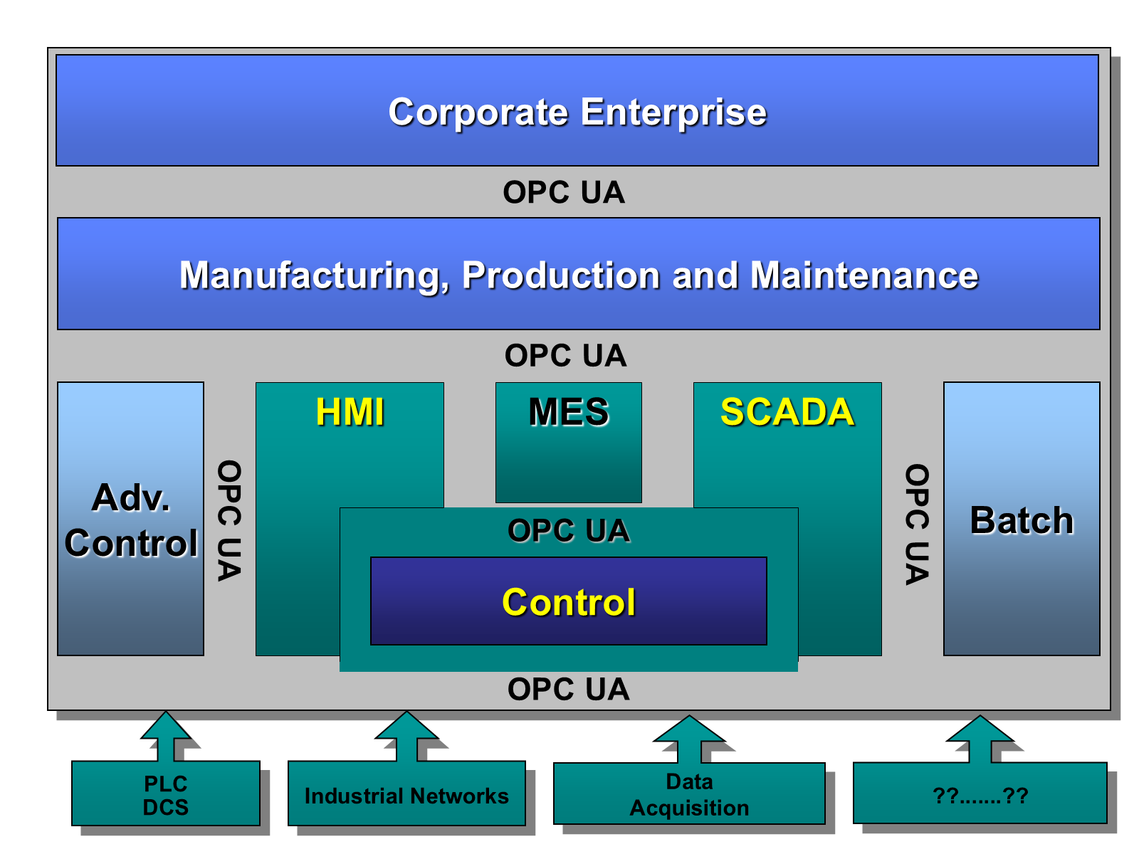
Widely used examples include Modbus RTU, Modbus TCP, EtherNet/IP, OPC UA, MQTT, and DNP3. Each serves different applications, but broad industry support gives facility owners more choices when designing, expanding, or servicing a system.
Choice
Reduce vendor lock-in
Proprietary communications can require specialized hardware, licensed software, or service from a single source. An open architecture gives owners access to multiple qualified suppliers and service providers, allowing decisions to be based on performance, availability, and cost.
Growth
Plan for future expansion
Industrial facilities rarely remain unchanged. Open standards can make it easier to add instrumentation, increase production, expand treatment processes, and upgrade equipment without redesigning the entire communications architecture.
Fit
Select better equipment
Engineers should be able to select a device because it meets the operational requirements, not because it is the only product capable of talking to an existing system. Open protocols broaden the field of proven industrial options.
Easier troubleshooting, less downtime
Standard protocols are familiar to technicians, engineers, and system integrators across the industry. Documentation, diagnostic software, and training resources are more widely available, making communication problems easier to identify and replacement equipment easier to source.
Service teams are less dependent on proprietary diagnostic tools, which can shorten troubleshooting time and help restore operations faster.
Protecting a long-lived investment
Automation systems often remain in service for twenty years or more. During that time, computers, operating systems, servers, networking equipment, and software platforms will continue to evolve.
A system built around open communication standards is better positioned to adapt without complete replacement. Individual components can often be modernized while preserving the overall architecture, extending useful life and reducing future modernization costs.
Building systems that last
Long-term value should not create long-term limitations
Open communication protocols help facilities remain flexible, maintainable, and prepared for future expansion. They reduce dependence on proprietary solutions while giving owners greater control over how their systems are serviced and upgraded.
A well-designed automation system should continue serving the facility for decades. Choosing open standards during design is one of the best ways to help make that possible.