INFRASTRUCTURE RESILIENCE
Building Resilient Water Infrastructure for an Uncertain Future
Water systems are expected to run every hour of every day. Storms, power loss, aging equipment, staff turnover and cyber threats challenge that expectation. Resilience is how a system responds on its hardest day.
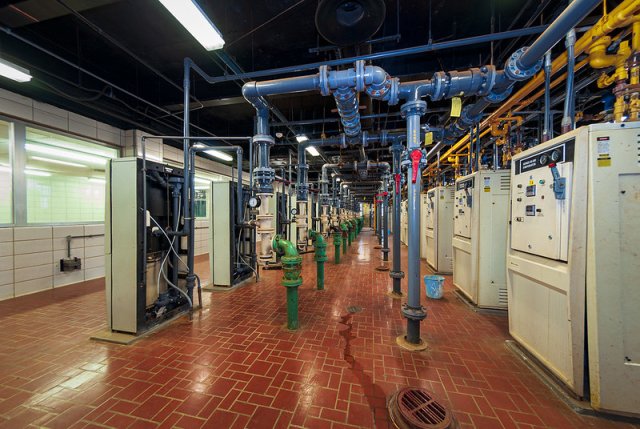
Resilience is not a single upgrade
No one product makes a plant or lift station resilient. Resilience comes from coordinated layers of power, local control, communications, recovery resources and trained people. Each layer should reduce the consequences when another becomes unavailable.
Start with a practical question: if this part of the system fails, what happens next? The answer should guide the design, documentation and testing.
Start with power
Every control system depends on power. Ask what happens when the utility feed drops: does the station ride through, restart cleanly, or require operator intervention? Generator transfer, UPS-backed controls and restart logic all need to match the process. A station that returns in the wrong state can create a second problem after the outage.
Check: Document the expected sequence for power loss, transfer and restoration, then verify it under an approved test plan.
Keep local control working
Design essential station control to operate without a remote server or SCADA connection. Pump alternation, backup level inputs and local alarm logic should be evaluated at the controller level. Loss of supervisory communications should not remove the local functions needed to operate safely.
Check: Define which functions continue locally and how operators recognize a communications failure.
Plan for a device failure
A resilient control design assumes a sensor or controller component may fail. Redundant level sensing, hard-wired backups and manual modes can provide additional layers when their independence and failure behavior are considered. A second sensor alone does not guarantee that a bad reading will be detected.
Check: Review sensor disagreement, backup operation and manual control while preserving required protective functions.
Give communications a backup plan
Radio, cellular and fiber links can all become unavailable. Consider more than one alarm path where the application warrants it, and examine whether those paths share power or infrastructure. Keep local control working while the link is out, and make loss of communication clear to operators.
Check: Identify who receives a lost-site alarm and what action follows.
Treat cybersecurity as another layer
Segmented networks, firewalls, controlled vendor access and tested backups each contribute to protection. Give vendors access only when needed, through a segregated path and for the authorized session. Design each layer with the assumption that another may fail.
Check: Review remote access arrangements and confirm that recovery copies are available when normal systems are unavailable.
Keep system knowledge available
Maintain current drawings, controller and HMI program backups, and network diagrams. Keep protected copies off-site and update them as systems change. Clear panel, wire and device labels help the next person troubleshoot. When experienced staff leave, the knowledge should stay with the utility.
Check: Confirm that another qualified team member can locate and understand the latest documentation.
Keep spares and test recovery
A spare is useful only if it works and fits the application. Identify critical controllers, power supplies, communication modules and HMI components, then choose spares based on operational risk and replacement lead time. Track obsolete parts and their replacement paths. Test backups and restores before an emergency.
Check: Verify that spare hardware, firmware, software and saved configurations support the planned recovery.
Modernize in stages
Replacing everything at once is rarely practical. Start with the highest-risk equipment and single points of failure. Standardize on platforms the team can support, and plan each stage to fit the next one. Temporary arrangements during an upgrade deserve the same attention as the final system.
Check: Connect each proposed upgrade to a specific failure scenario and a practical implementation sequence.
Train the people
Operators need clear procedures for abnormal conditions and manual operation. Practice outage response and recovery through planned drills suited to the site. Technology supports the response, but people must understand what the system is doing and when to intervene.
Check: Walk through responsibilities, escalation contacts and the return to normal operation.
How can BEA help?
BEA designs and supports PLC and SCADA controls for water and wastewater systems. We assess existing lift stations and plants for single points of failure, help utilities plan staged upgrades around real budgets, and document systems so the team can maintain them with confidence.
If you want a second set of eyes on your system, give us a call. Start with one station or one failure scenario, then build a practical improvement plan.
PID vs. Pseudo-Loop: Choosing How to Control the Process
A control loop should reflect the physics of the process, not just the name of the instruction. PID is an established choice for continuous regulation, but some applications benefit from an explicit step-and-wait strategy built around deadbands, timers, output increments, and exception rules. At Britton Electronics & Automation, we use the descriptive term pseudo-loop for that rule-driven approach.
What Is a Pseudo-Loop?
A pseudo-loop imitates continuous control through programmed decisions rather than proportional, integral, and derivative equations. It can use variable deadbands, variable timers, exception rules, fast overrides, preset starting points, incremental output adjustments, and conditional logic.
The deadband determines when an adjustment is needed, the increment determines how much the output changes, and the timer determines when another adjustment is permitted. Each can vary with error size, direction, equipment state, or information from another process.
Pseudo-loop is a descriptive term, not a standardized algorithm. Modern PID instructions, including enhanced controllers such as Rockwell Automation's PIDE, can also provide tracking, feedforward, limits, anti-windup, and mode management. The distinction is whether the primary regulation strategy is expressed through a tuned control equation or through explicit process rules.
Asymmetric Control: Bump Up and Bump Down
A pseudo-loop can use different adjustments in each direction. Consider a pump maintaining 60 PSI:
| Process condition | Output adjustment | Wait time |
|---|---|---|
| Below 59 PSI | Increase 2.5 percentage points | 10 seconds |
| 59–61 PSI | Hold output | No adjustment |
| Above 61 PSI | Decrease 3.0 percentage points | 10 seconds |
Illustrative settings, not recommended tuning values. Output changes are percentage points of the command range.
The larger downward step prioritizes reducing excessive pressure; the smaller upward step does not immediately undo the entire previous reduction. Combined with appropriate deadbands and waiting intervals, asymmetric adjustments can reduce hunting. They do not guarantee stability: the process response still determines appropriate increments and delays.
Near setpoint, a strategy might use smaller steps and longer waits. Farther from setpoint, it might use larger steps and shorter waits. The table shows only one band in each direction for simplicity.
Where Explicit Rules Can Help
Dead Time
In chemical dosing, a change at the injection pump may take time to reach a downstream analyzer. Repeated increases before the first change is measured can cause overdosing. A pseudo-loop can make an adjustment, wait for transport and settling time, then reevaluate. The wait can vary with measured flow. Conventional PID can also manage dead time with appropriate tuning, feedforward, or specialized compensation.
Equipment Staging
When a lag pump starts, the controller can suspend upward adjustments, select a new preset output, and change its waiting interval while header pressure stabilizes. Similar rules can respond to valve movement, backwash cycles, or demand changes.
Unreliable Inputs and Communications
A transmitter reading zero, full scale, or changing implausibly needs a defined response. Depending on the process, the controller might hold, use a validated redundant measurement, enter a restricted mode, or shut down. Loss of communications to a drive or remote I/O also needs a defined response. Holding the last output is not automatically safe.
Output Limits and Fast Overrides
If a pump reaches maximum speed while pressure remains low, further upward adjustments should not accumulate. The controller may alarm, request additional equipment, or change strategy. A high-pressure override may bypass the normal increment timer and command a larger immediate reduction, coordinated with any independent protective functions.
Transitions and Priorities
Suppose a 2.5-point upward bump is pending when a high-pressure override activates. The override takes priority; the pending bump must be canceled or explicitly suspended. When the override clears, the controller should track the actual output and deliberately resume, wait, or reinitialize. Setpoint changes, manual-to-auto transfers, and communications recovery also need defined transitions.
Windup and Output Tracking
A PID without effective anti-windup or tracking can accumulate integral error while its final output is constrained. When the constraint clears, that accumulated demand can cause an unexpected response. A pseudo-loop has no conventional integral term, but queued increments can create a similar problem. Both strategies need to cancel inappropriate adjustments, track the actual equipment command, and return to normal control under defined conditions.
Retuning and Portability
A well-structured pseudo-loop is easier to reason about. Deadbands, step sizes, and waiting intervals correspond directly to observable process behavior, so a technician can often adjust them without developing a mathematical process model. Those basic parameters can also be relatively portable between PLC platforms when scaling and execution timing are equivalent. PID parameters may differ between implementations because of equation form, time units, and scaling. Neither approach is plug-and-play: commissioning, documentation, and testing remain essential, particularly when changes affect exception priorities or equipment transitions.
Troubleshooting the Ghost Variable
A PID may calculate 65% pump speed while another routine limits the final command to 50%. Another routine may change the setpoint, and another may adjust the gains. All may be legitimate, but the technician examining only the PID cannot explain the actual pump command.
The same problem can occur in a pseudo-loop with scattered, undocumented exceptions. The important question is which routine currently owns the output, and why?
A technician should be able to see:
- Current mode and active control strategy.
- Process variable, setpoint, and error.
- Requested output and actual commanded output.
- Active deadbands, increments, and timers, when applicable.
- Output limits, overrides, and exception priorities.
- The condition responsible for the most recent output change.
Good diagnostics make the entire chain of authority visible, not just the instruction on the screen.
Choosing the Right Strategy
Conventional PID
Continuous regulation with understood dynamics, including many pressure, flow, temperature, and level applications.
Pseudo-loop
Deliberate step-and-wait behavior, independently configured upward and downward responses, significant or variable dead time, and process-specific exception handling.
Hybrid
PID performs normal regulation while supervisory logic manages staging, startup, shutdown, operating modes, and exceptions.
A hybrid design needs deliberate handoffs. When supervisory logic takes control, the PID should receive appropriate tracking or mode information so two routines do not compete for the same output.
Control the Process, Not Just the Error
PID, pseudo-loop, and hybrid control are not mutually exclusive. A facility can use each where it fits. The choice should account for dead time, interacting processes, equipment limits, abnormal conditions, and maintainability from the beginning.
The process doesn't care what the routine is named. It responds to equipment physics and the control decisions programmed around it.
How Can BEA Help?
Britton Electronics & Automation helps evaluate process behavior, define control authority, organize exception handling, improve operator visibility, and commission PID, rule-driven, or hybrid strategies. The goal is a control system that performs predictably and remains understandable to the people who support it.
Britton Electronics & Automation Inc. | Industrial Automation, System Integration & Troubleshooting

Industrial Automation and Controls
NEMA vs. IEC: Why the Difference Exists, and Should You Care?
Open two industrial control panels and you may find very different motor starters doing essentially the same job. One may be a larger NEMA starter with broad application margin. The other may be a compact IEC contactor selected closely for the motor and switching duty. Both can be correct.
The useful question is not which one is better
NEMA and IEC represent different approaches to the same engineering problem. Traditional NEMA equipment is organized around standardized starter sizes. IEC equipment is generally selected more closely around the load, operating duty, and utilization category.
The practical question is whether the selected device, protective components, and application remain a valid system.
Two approaches to motor control
NEMA approach
Standardized starter sizes can simplify selection and provide useful application margin. A facility may also standardize around fewer starter sizes for emergency replacement and storeroom planning.
Representative family: Eaton Freedom NEMA contactors and starters, including non-reversing and reversing configurations and overload options.
IEC approach
Selection is commonly tied more closely to the motor, load type, switching duty, operating voltage, and utilization category. The result can be a compact, modular installation with more application-specific choices.
Representative family: Schneider Electric TeSys Deca contactors, offered for motor and non-motor loads in non-reversing and reversing arrangements.
Product families are examples, not drop-in replacement recommendations. Final selection depends on the complete application and the manufacturer's current selection data.
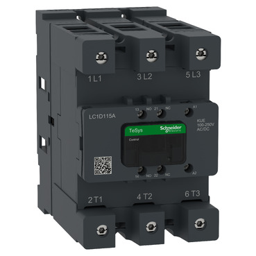
The amp rating does not tell the whole story
An 18 A marking does not by itself establish suitability. Schneider Electric's own TeSys example shows why: an LC1D18 contactor is associated with 18 A motor duty in AC-3, while the same family can have a different current rating for resistive AC-1 service.
Load type and switching conditions change what the contacts must make and break. Always compare the correct utilization category, motor rating, voltage, coil, poles, duty, and environmental conditions.
Review Schneider Electric's explanation of AC-1 and AC-3 utilization categories.
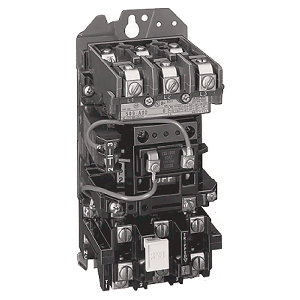
A NEMA starter by sight
This Allen-Bradley Bulletin 509 example shows the larger assembled form many technicians associate with a traditional NEMA starter. The contactor and overload are presented as a starter selected around a standardized NEMA size.
Appearance can help identify the design approach, but it does not establish interchangeability. Confirm the NEMA size, motor horsepower and voltage, coil voltage, overload range, enclosure, duty, and coordinated protection before selecting a replacement.
What the utilization categories mean in practice
AC-1: resistive or slightly inductive loads
Typical examples include resistance heating and distribution loads. This is not the same switching duty as starting and stopping a motor.
Product example: A TeSys Deca contactor selected from its published AC-1 rating for a heater application.
AC-3: common motor starting duty
Used for squirrel-cage motors where the contactor starts the motor and opens while the motor is running, such as pumps, conveyors, compressors, and mixers.
Product example: A TeSys Deca LC1D family contactor selected by its AC-3 motor rating at the actual system voltage.
AC-4: jogging, inching, or plugging
Frequent starts, plugging, and inching impose a more severe duty. A contactor that is adequate for ordinary AC-3 service may require different sizing for AC-4 operation.
Product example: A manufacturer-rated TeSys contactor selected from the AC-4 tables, not merely from the AC-3 nameplate current.
Reversing service
Forward and reverse operation requires a properly selected reversing arrangement with suitable mechanical and electrical interlocking, overload protection, and control logic.
Product examples: Eaton Freedom reversing NEMA starters or Schneider Electric TeSys Deca reversing contactors, selected as complete arrangements.
Why IEC equipment can be smaller
A compact IEC contactor is not automatically underbuilt. It may be selected more specifically for the load and operating conditions instead of carrying the broader application margin associated with standardized NEMA sizes.
Panel advantage
A smaller footprint can reduce enclosure space, improve component layout, or reserve room for future equipment.
Selection responsibility
When the motor, duty cycle, reversing requirements, or process changes, the original selection assumptions must be checked again.
Inventory tradeoff
Closely matched IEC selections may create more distinct contactor and overload combinations. NEMA standardization may allow broader coverage with fewer starter sizes.
NEMA's extra margin can be useful
Industrial machines rarely live exactly as shown on their original drawings. Motors are replaced, loads change, and occasional operation can become frequent cycling. Additional application margin can be useful, especially where maintenance teams have standardized around a small set of starter sizes.
Eaton's Freedom NEMA family is a useful real-world example. Eaton organizes the line around standard NEMA classifications and offers contactor, starter, reversing, overload, enclosure, and accessory choices. That does not make every Freedom device interchangeable. It illustrates the NEMA sizing and maintenance philosophy.
Replacement is where the difference matters most
A failed contactor at 2:00 AM can make a physically similar spare look attractive. Before installing it, verify more than coil voltage, pole count, and current.
Load and duty
- What type of load is being switched?
- What are the motor horsepower and voltage?
- Which utilization category applies?
- How often does it operate?
- Does it jog, plug, or reverse?
Protection and coordination
- How is overload protection configured?
- What branch-circuit protection is upstream?
- What is the available fault current?
- Was the starter part of a tested or listed combination?
- Does the replacement preserve the panel's ratings?
Fit and support
- Are terminals, conductors, spacing, and heat dissipation suitable?
- Are auxiliary contacts and control functions equivalent?
- Is current manufacturer documentation available?
- Can the correct spare be stocked and identified clearly?
Coordination matters too
A motor starter is part of a system that includes the contactor, overload device, branch-circuit protection, disconnecting means, conductors, motor, and available fault current. Changing one component can affect more than normal operating current.
In a UL 508A listed panel, the short-circuit current rating depends on component ratings, combinations, and protection. A contactor with adequate horsepower and current ratings is not automatically an acceptable substitution within the combination used to establish the panel SCCR. The modification should be reviewed against the applicable manufacturer's coordination data, panel documentation, and listing requirements.
Spare parts are an engineering decision
When standardization leads
A facility with many motors may value a limited set of familiar NEMA starter sizes, documented heater or overload selections, and readily identifiable emergency spares.
When space and modularity lead
A facility with constrained enclosures and an established IEC product family may benefit from compact components, DIN-rail practices, coordinated selections, and modern configurable overloads.
Panel space, inventory, training, lifecycle support, and downtime all have a cost. Good design considers them together.
Most modern panels are already a mixture
A North American panel may use a NEMA enclosure, North American wiring conventions, IEC-style contactors, DIN-rail terminals, and products carrying multiple approvals. That is normal. The objective is not to make every component belong to one camp. It is to build a safe, maintainable system in which each component is suitable for its application.
So, should you care?
Yes, because the differences affect how equipment is selected, replaced, protected, stocked, and maintained. For a new panel, they influence component sizing, enclosure space, coordination, spare parts, and future expansion. For an existing system, they help prevent a physically compatible replacement from becoming an electrically inappropriate one.
The important part is not choosing a side. It is understanding what the ratings mean, what the application requires, and why the component belongs in the system.
How can BEA help?
BEA can review motor-control applications, identify installed components, verify load and duty requirements, evaluate overload and short-circuit protection, check current manufacturer selection data, and help develop a practical spare-parts strategy.
Whether the panel uses NEMA, IEC, or a mixture of both, we help customers make replacements and upgrades as system decisions, not part-number guesses.
A whole-cabinet approach to aging controls
The PLC Is Usually Not the First Thing We Replace
Open an older control cabinet and the PLC is the component everyone recognizes. It may also be one of the more stable parts of the system. The immediate risk is often in the aging equipment around it.
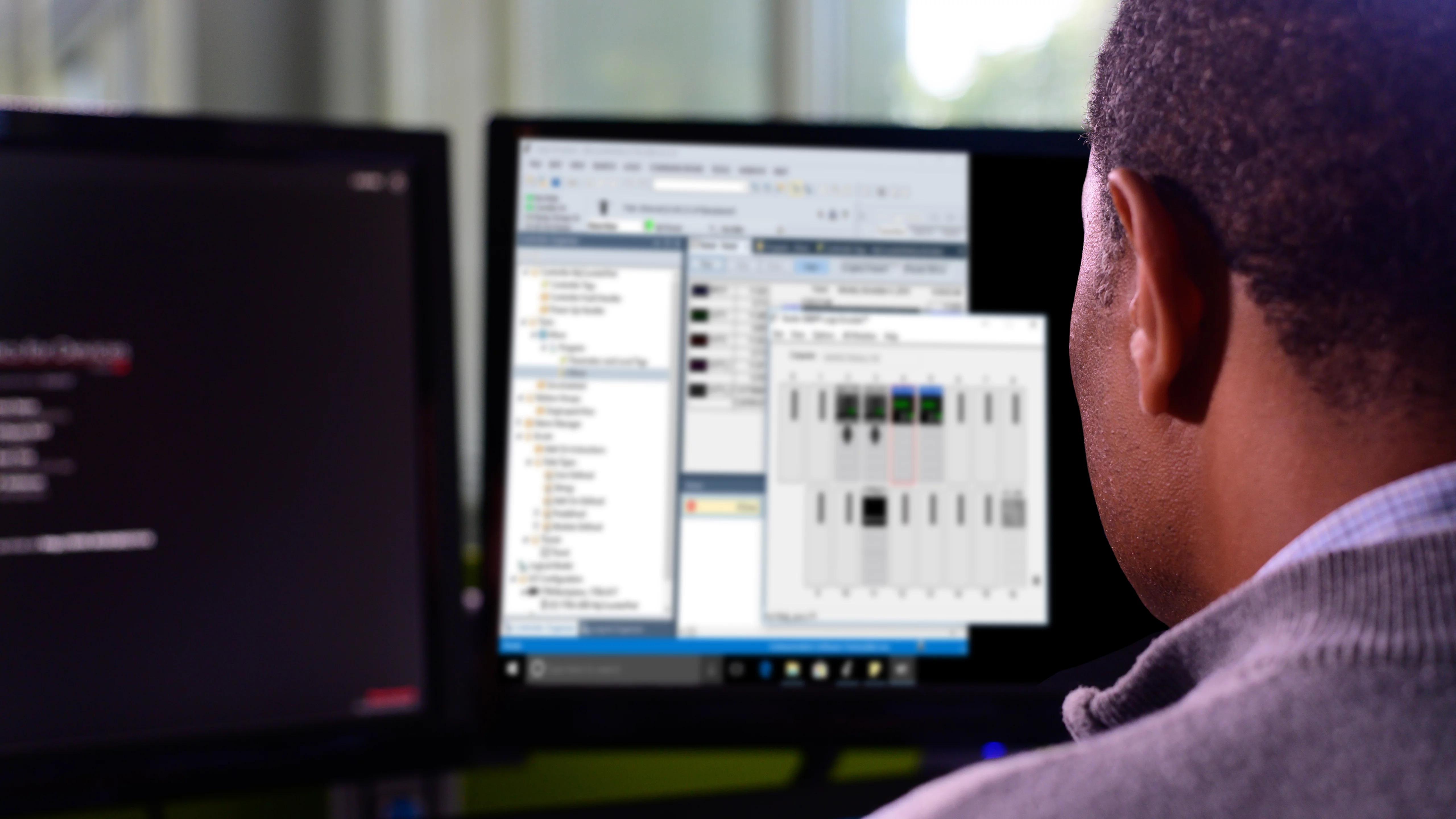
A cabinet should be evaluated as a connected system. Controller age is only one part of the modernization decision.
One cabinet, several generations
A moderately aged PLC can share an enclosure with much older relays, brittle wiring, tired cooling equipment, obsolete communication hardware, weak power supplies, and field devices that have survived years of heat and vibration.
Replacing the controller first may leave the most likely interruption points untouched. It can also turn a limited repair into a larger commissioning project before the plant is ready.
Start with evidence, not appearance
Age matters, but condition, supportability, failure history, process consequence, and available spares matter more. Before selecting a replacement target, document what is installed, review alarms and maintenance records, inspect the cabinet, verify power quality and loading, and identify components that can no longer be supported predictably.
The best first project is the one that removes the largest practical risk with a controlled amount of change.
What often deserves attention before the PLC
Control power
Power supplies, transformers, protection devices, and loose or deteriorated connections can affect every device downstream. Verify voltage behavior under real operating conditions.
Heat and contamination
Blocked filters, failed fans, damaged enclosure seals, and accumulated contamination shorten component life. Correcting the environment may protect the entire installed system.
Relays and contact devices
Mechanical switching components wear with use. Repeated nuisance failures, damaged sockets, and unclear labeling can justify focused replacement and documentation.
Networks and interfaces
Old switches, converters, connectors, and unsupported communication paths may be harder to diagnose or replace than the controller itself.
Operator interface
An obsolete HMI, unavailable programming software, or missing project file can create a support problem even while the PLC continues to run reliably.
Field wiring and devices
Sensors, instruments, solenoids, terminal blocks, and cable terminations live at the edge of the system, where moisture, vibration, and physical damage are common.
Four questions for a sensible replacement sequence
- What is failing now? Use service records, alarms, inspection, and testing to identify recurring problems.
- What cannot be recovered? Confirm backups, source files, software access, spare availability, and a tested restoration path.
- What stops the process? Rank components by operational consequence, not only by purchase date.
- What change can be tested safely? Plan isolation, simulation, factory testing, rollback, and a realistic outage window before touching production equipment.
When the PLC should move to the front
A controller migration becomes urgent when hardware support and spares are no longer dependable, engineering access cannot be maintained, required expansion is impractical, communications constrain the application, or the platform creates an unacceptable recovery or cybersecurity risk. Even then, the project should include the I/O, power, network, HMI, software, documentation, and field interfaces that determine whether the new controller will succeed.
Rockwell Automation describes proactive lifecycle planning as an assessment and migration process, and notes that parts and skilled support for discontinued PLC-5 systems are becoming scarce. That is a useful reminder that modernization should be planned before an emergency, while the existing process can still be studied and tested. Review Rockwell Automation's PLC-5 migration resources.
A practical phased path
1. Stabilize
Correct active power, cooling, wiring, and component problems. Capture backups and preserve evidence.
2. Document
Record hardware, networks, I/O, software versions, drawings, dependencies, spares, and recovery procedures.
3. Prioritize
Rank risks by likelihood, consequence, supportability, and the effort required to make a controlled change.
4. Modernize
Execute the approved scope with backups, test plans, operator input, commissioning records, and a defined rollback strategy.
How can BEA help?
BEA can assess an aging cabinet as a complete operating system, not a collection of part numbers. We help customers inventory installed equipment, troubleshoot current weaknesses, recover and document programs, evaluate lifecycle risk, and build a phased modernization plan around production needs.
If an older panel is becoming harder to support, we can help determine what should be replaced first, what can remain in service, and how to make the change without creating avoidable downtime.
Simple Ways to Plan Your Automation Today So It Can Grow Tomorrow
Nobody knows exactly what a plant will need five or ten years from now. Another pump may be added. Production may increase. A remote site may come online. Operations may want more data. An older piece of equipment may finally need replacement.
You cannot design for every possibility, but you can avoid designing yourself into a corner. A few practical decisions during the original project can preserve useful options when the first expansion arrives.

Plan for options, not predictions
Future-ready design does not mean buying equipment that may never be used. It means considering physical space, electrical capacity, communications, programming structure, and documentation while changes are still inexpensive to accommodate.
The goal is simple: make the next addition an extension of the system, not a reason to redesign it.
Six decisions that make growth easier
1. Leave some room
A panel filled from top to bottom on day one offers few good expansion options. Consider spare DIN rail, usable wireway space, power supply capacity, heat load, and a reasonable amount of spare I/O.
Outside the panel, consider whether extra conduit, pull space, or fiber capacity can be installed economically during construction.
2. Build a network
Think beyond a collection of individually connected devices. Consider where another PLC, VFD, remote I/O rack, HMI, or instrumentation network could fit and how traffic, addressing, security, and remote connectivity would be managed.
3. Use standards early
Consistent PLC tags, device names, IP addressing, wire numbers, alarm conventions, and equipment numbering may seem excessive on a small system. They become valuable as the number of controllers, devices, and people grows.
4. Keep logic understandable
Organize control logic by equipment or process function. Use meaningful names, understandable sequences, and clear interfaces. Avoid unnecessary dependencies between unrelated parts of the system.
5. Keep documentation alive
Electrical drawings, network diagrams, I/O lists, PLC comments, HMI documentation, and equipment settings should change when the system changes. Documentation is part of the control system, not an optional record created at the end.
6. Choose flexibility where it matters
When two reasonable equipment choices exist, ask whether the device can communicate with likely future systems, accept another module, expose useful data, and remain supportable through the expected lifecycle.
Turn expansion into an architecture question
Before selecting components, sketch how the system could change. Where would added I/O connect? Which switch port, enclosure, power supply, controller resource, and network segment would support it? Would operators need another HMI view? Who would update backups and drawings?
This exercise does not lock the plant into one future. It reveals low-cost provisions that preserve several possible futures.

A practical planning review
Physical capacity
- Is there accessible rail and wireway space?
- Can the enclosure manage added power and heat?
- Are conduit, cable tray, and fiber routes expandable?
- Can future work be completed safely around operating equipment?
Control and network capacity
- Is spare I/O appropriate for likely additions?
- Are controller, HMI, and network resources understood?
- Is the addressing and naming plan documented?
- Can remote sites or new equipment be segmented appropriately?
Lifecycle capacity
- Are programs and configurations backed up?
- Do drawings and device lists match the installed system?
- Can another engineer understand the code and sequences?
- Are platform support and migration considerations recorded?
Do not confuse spare capacity with an engineering decision
Available panel space, I/O, network bandwidth, or controller memory does not automatically make an addition suitable. Each change still needs application review, electrical and thermal checks, network and cybersecurity consideration, and any required safety or code evaluation.

Make the handoff usable
Future expansion often happens years after the original project and may involve a different engineer, integrator, or maintenance team. A clean program structure and current documentation give that team a reliable starting point.
Record not only what was installed, but also the conventions used, reserved addresses, spare capacity, known limits, and decisions that may affect later work.
The bottom line
Future-proofing automation is not about predicting the future. It is about making sure the future still has options.
Leave practical room, create an expandable architecture, use standards before they feel necessary, write logic another person can follow, keep documentation current, and choose flexibility where it has real application value. Those decisions can turn a disruptive redesign into a manageable expansion.
How can BEA help?
BEA helps industrial and municipal facilities plan control panels, PLC and HMI platforms, industrial networks, remote I/O, standards, documentation, and phased modernization. We can review current requirements alongside likely growth scenarios and help identify practical provisions without overbuilding the first project.
For an example of a scalable control and information framework, see Rockwell Automation's Integrated Architecture overview.
The Hidden Cost of Deferred Maintenance in Critical Infrastructure
A raw water pump runs 600 hours past its grease interval. A PLC low-battery alarm is acknowledged and forgotten. A control-panel exhaust fan keeps rattling on worn bearings.
None of these conditions stops the plant today, so each can appear easy to postpone. The cost does not disappear. It moves downstream, where it is often more expensive and harder to control.
Planned work costs less than reactive work
1. Scheduled maintenance
Parts, staffing, downtime, backups, and operating coordination can be arranged before work begins. The interruption is expected and controlled.
2. Deferred servicing
Wear continues, cooling declines, connections loosen, batteries lose capacity, filters load, and nuisance trips appear. The asset still runs, but its reliability margin is shrinking.
3. Emergency failure
The facility now faces an unplanned outage, emergency labor, expedited freight, temporary procedures, production loss, or damage beyond the original maintenance item.
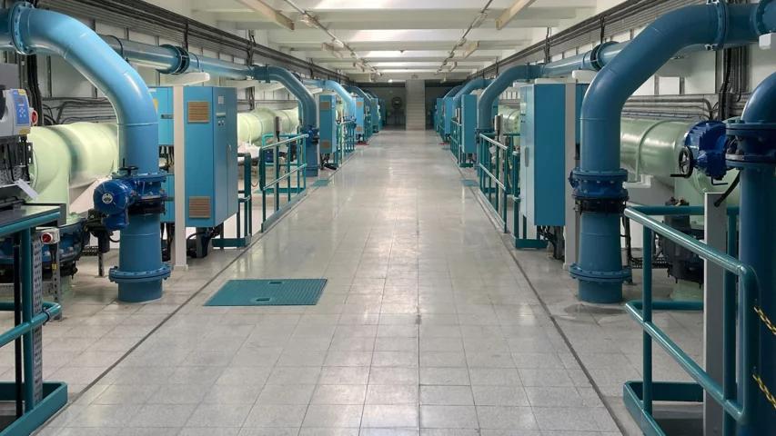
Where hidden costs live
A maintenance backlog rarely appears as one clean expense. It spreads into the surrounding equipment, supply chain, staff knowledge, recovery plan, and operating risk.
The original task may be inexpensive. The consequences of waiting may not be.
Collateral damage
A failed panel fan can expose a VFD, power supply, or PLC enclosure to excess heat. A leaking seal can affect nearby wiring or instrumentation. A loose connection can damage terminals, conductors, breakers, and enclosures.
Supply-chain exposure
PLCs, VFDs, safety devices, communication modules, and breakers may have long lead times or limited availability. Older components may be available only through surplus channels or brokers.
Lost institutional knowledge
Undocumented operating sequences, drive settings, logic changes, and recovery steps leave a facility dependent on the continued availability of particular people.
Safety and regulatory margin
Ignored alarms, degraded instruments, missed calibrations, and poorly maintained protective devices can reduce margin until several small problems align at the wrong time.
Recoverability is part of maintenance
A control system can operate normally and still be difficult to recover. A missing PLC backup, an HMI project stored only on an old laptop, unsaved VFD parameters, outdated network records, or inaccurate electrical drawings may not affect today's production. Each missing item can add hours or days after a failure.
Redundancy has to be maintained too
Two pumps, standby equipment, backup generators, spare drives, redundant communication paths, and shelf spares only reduce risk when they are ready to work.
Exercise it
Run standby pumps, test backup power, and verify alternate communication paths on a planned schedule.
Inspect its condition
A backup VFD in fault or a generator with a weak starting battery provides little protection during an outage.
Keep it deployable
A spare PLC without the current program is only hardware on a shelf. Store the software, parameters, cables, licenses, and instructions required to put spares into service.
Age alone does not define reliability
Older equipment can remain dependable when it was installed correctly, maintained properly, documented, and supported with usable spares. Newer equipment can create problems when it is overloaded, poorly installed, exposed to excessive heat, or neglected.
Ask risk-based questions
- Can the equipment still be supported, and are replacement parts available?
- Is there a tested, usable spare?
- Are PLC and HMI programs, drive parameters, and drawings current?
- Does more than one person understand how the system operates?
- What happens to the process if this asset fails?
- How long would a safe recovery take?
Why the backlog builds
Visible projects win budgets
Capital improvements are easy to identify, while routine maintenance competes quietly with other funding needs.
Running gets confused with reliable
Equipment can continue operating while its reliability margin steadily decreases.
Staffing stays reactive
Preventive work is often postponed when limited maintenance staff spend most of their time on current problems.
Deferred work loses ownership
Tasks held in notes, emails, or memory are difficult to prioritize and easy to forget.
Breaking the reactive cycle
Audit the critical path
Prioritize assets whose failure could stop the process, create a safety concern, eliminate redundancy, or require a difficult recovery.
Standardize practical spares
Where practical, standardize frequently replaced power supplies, relays, contactors, fuses, cooling fans, UPS batteries, and communication hardware. Verify that every spare fits the intended application.
Upgrade incrementally
Create migration plans for equipment with poor supportability, unavailable parts, missing backups, or serious process consequences. Planned modernization is easier to control than emergency modernization.
Protect the schedule
When work must be postponed, keep it visible, evaluate the consequence, assign ownership, and set a new date instead of allowing it to disappear.
The bottom line
Deferred maintenance can look inexpensive while equipment is still running. Its real cost appears later through reduced reliability, emergency labor, collateral damage, missing spares, difficult recovery, and operational risk.
Good maintenance cannot guarantee that nothing will fail. It makes failures more predictable, recovery more manageable, and emergency decisions less common. Reliable facilities deal with small problems while they are still small.
How can BEA help?
BEA helps water, wastewater, and industrial facilities assess control-panel health, plan PLC and HMI lifecycles, review backups and documentation, troubleshoot control systems, and build preventive maintenance strategies around the equipment and processes that keep the facility operating.
Why I Show Up to City Council Meetings as an Engineer, Not Just a Resident
Most people who show up to a city council meeting are there for something that directly affects their neighborhood. I tend to notice the four-minute agenda item almost nobody else in the room fully understands.
A line item approving remote access upgrades at the water plant. A vendor change for the SCADA system that runs it. A communications upgrade between a well site and the treatment plant.
Those items can move fast. They are scheduled between a parking ordinance and a parks budget update, and sometimes they pass without a single technical question. That is the part that gets me in the car.
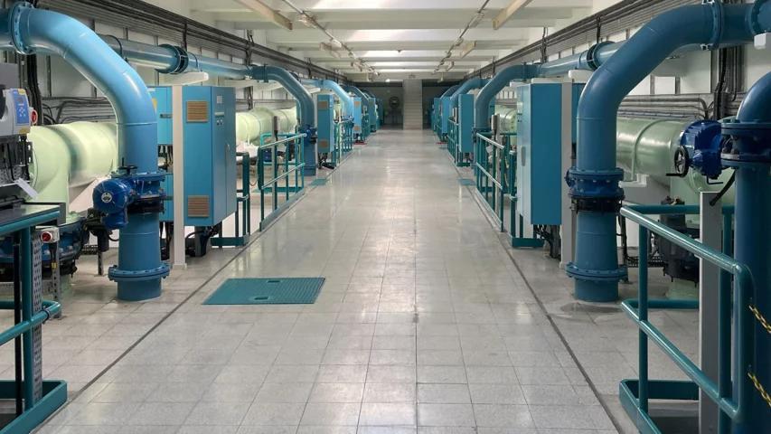
Water treatment plants depend on coordinated pumps, controls, communications, and secure support practices. Image: Rockwell Automation.
The Four Minutes Nobody Understands
When remote access comes up, the useful questions are practical. They are the same questions a control systems engineer should ask before signing off on a project.
Council members weigh budgets, policy, priorities, and community needs. They are not expected to evaluate industrial network architecture. Plant personnel may be operating an entire utility with limited staffing. The vendor is there to propose and deliver a system. Independent technical scrutiny still matters.
Identity and access
Does remote access require multi-factor authentication? Who has access, and how is that access removed when a person or vendor no longer needs it?
Network path
Where does the connection terminate? Does it land on a controlled jump host, or create a path toward the network communicating with PLCs?
Lifecycle support
Will the vendor still support the HMI or SCADA software five years from now, or is the municipality buying a difficult migration for 2031?
These are not exotic questions. Yet in a council chamber, nobody may have the specific job of asking them. Sometimes the questions simply do not get asked. They cost nothing to ask in the room, and they can cost a great deal to skip.
What Skipping Them Can Cost
In July 2026, Minnesota officials reported malicious cyber activity targeting technology at more than 30 community water systems. Most confirmed cases involved technology used to remotely monitor or control equipment.
That is why the architecture behind remote access matters. The answer is rarely as simple as buying a better firewall after something happens. The better starting point is months or years earlier, when someone asks how access is designed, who will maintain it, what protections are in place, and what happens when a component fails.
By the time an infrastructure system appears in an incident report, the decision that mattered may have been made long before. Sometimes it was part of a five-minute agenda item that nobody thought needed another question.

Automated pumping and treatment equipment depends on reliable controls, communications, and support practices. Image: Rockwell Automation.
This Is Not About Slowing Anything Down
I am not at these meetings to embarrass anyone or throw sand in the gears of a project that has already been properly vetted.
Most of the time, the answer to my question is perfectly reasonable, and the meeting moves on exactly as it would have anyway. I am there because I understand what is actually being decided.
Evaluating remote access architecture is not something most residents are expected to do. It is what I do professionally.
What Technical Residents Can Contribute
Listen for operational technology
Notice agenda items involving SCADA, HMI, PLCs, telemetry, cellular communications, remote support, or vendor access.
Ask one clear question
Focus on an important control such as MFA, segmentation, access removal, logging, fallback operation, or long-term support.
Respect the room
The goal is to improve a decision, not perform a technical cross-examination. A concise question can reveal whether the issue has already been addressed.
If you are an engineer, IT professional, operator, or someone who has spent time around OT systems, sit in on a city council or utility board meeting sometime, even if you only watch.
You may be surprised how many real infrastructure decisions are made in a matter of minutes by people who may never personally see the equipment they are approving money for.
Showing up does not fix everything. But it can mean that at least one person in the room asks the question before it becomes an incident report.
Further reading: Minnesota IT Services update on community water system cyber activity and CISA and EPA guidance on internet-exposed HMIs.